Wind energy · Contactors
Wind Turbine Generator Contactor Overhaul
The stator, rotor and crowbar contactors in a turbine converter cabinet cycle on every start and stop. We overhaul the big frames — Schneider LC1F, ABB AF and A-series, Siemens 3RT and 3TF — to OEM wear limits, and test every one for pick-up, drop-out and contact resistance before it goes back.
- Frames265 – 2100 A
- ScopeContacts · coils · poles · chutes
- TestingPick-up, drop-out, mΩ per pole
- Warranty12 months
The problem
A contactor rated for a million operations gets there quickly in a turbine
The generator contactor connects the stator to the grid when the turbine reaches synchronous speed and drops out on every stop — grid event, high wind cut-out, curtailment, maintenance. The rotor-side and crowbar contactors in a doubly-fed machine work harder still, switching under the converter's control during ride-through. A frame that would last decades in a motor control centre is worn out in a few years of turbine duty.
What wears is well understood. Main contacts erode and pit until contact resistance climbs and the poles run hot. Springs lose pressure. Coils overheat in a cabinet that spends summer afternoons above 40 °C. Arc chutes crack and their splitters erode. Magnet faces pick up debris and the contactor chatters. Auxiliary blocks — which the controller relies on for feedback — fail intermittently long before the main poles do.
Overhauling the contactor addresses all of it at once, on a unit whose mounting, terminations and control wiring already match the cabinet. The alternative is a new contactor, which for the older frames means an OEM lead time and, often, a different footprint.
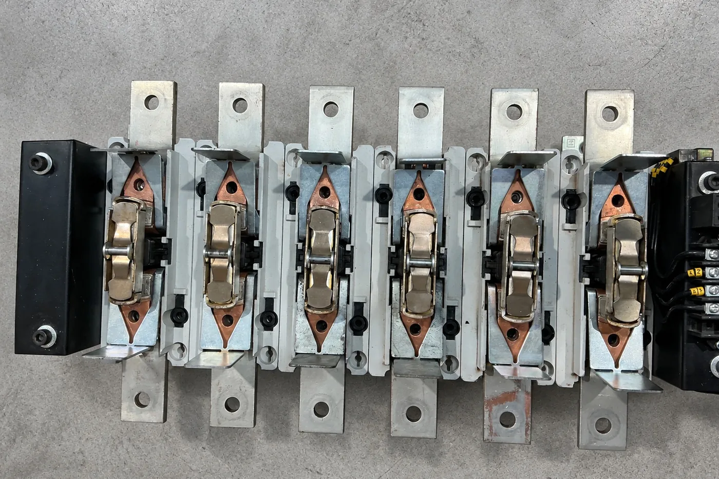
| Main contacts | Replaced as complete sets — fixed and moving — with new contact springs; pressure verified |
| Pole assemblies | Carriers inspected for heat distortion and cracking; replaced from donor stock where needed |
| Arc chutes | Inspected for cracking, splitter erosion and tracking; cleaned or replaced |
| Coil & magnet | Coil resistance and insulation tested; magnet faces cleaned and checked for shading-ring damage; coil replaced where marginal |
| Auxiliaries | Auxiliary contact blocks and interlocks tested and replaced — these are cheap and fail first |
| Terminations | Main terminals inspected for heat damage; re-plated or replaced |
| Test | Pick-up and drop-out voltage, contact resistance per pole, insulation resistance, mechanical operation, coil current |
Ranges
Contactor families in the turbine converter cabinet
Schneider TeSys LC1F
The 265 to 2100 A frames used as generator and crowbar contactors across a large part of the European-built fleet. Contact kits, coils, pole carriers and auxiliary blocks — a range we overhaul continuously, including for US customers.
LC1F265 · F330 · F400 · F500 · F630 · F780 · F800 · F1250
ABB AF and A-series
AF-series electronically controlled coils and the older A-series AC-coil frames. The AF coil electronics fail on supply transients; the A-series suffer classic magnet and shading-ring wear. Both are rebuilt.
AF265 – AF2650 · A260 – A300 · EK / EH series
Siemens 3RT and 3TF
3RT1 and 3RT2 frames on newer machines; 3TF6 on the older fleet. Contact sets, coils and arc chute assemblies, plus the 3RH auxiliary blocks that feed the controller.
3RT1075 – 3RT1476 · 3TF68 / 3TF69
Testing
What "tested" means for a contactor
A contactor that closes when you press it is not a tested contactor. Every overhauled unit is proved on the bench for the things that actually take a turbine off: pick-up voltage at the bottom of the coil's tolerance band, so it closes reliably when the control supply sags; drop-out voltage, so it releases when commanded and holds when it shouldn't; contact resistance measured per pole with a micro-ohmmeter, so the poles will run cool at full generator current; coil current and insulation resistance; and mechanical operation for chatter and bounce. Auxiliary contacts are proved in every position.
The results go on the certificate against the unit's serial number. Fit it, connect it, and the controller sees exactly what it saw with the original.
| Pick-up voltage | Measured; must close at or below the lower coil tolerance limit |
| Drop-out voltage | Measured; must release within the manufacturer's band |
| Contact resistance | μΩ / mΩ per pole at test current; balanced across poles |
| Insulation resistance | Pole-to-pole and pole-to-earth |
| Coil | Resistance and operating current at rated voltage |
| Auxiliaries | Every NO/NC block proved in both positions |
FAQs
Frequently asked
Is it worth overhauling a contactor rather than fitting a new one?
For the large frames, yes — the overhaul costs a fraction of a new unit and the OEM lead time on a 1250 A contactor is not something you want a turbine waiting on. For small frames in the pitch and yaw systems, a new contactor is often the right answer and we'll say so.
The contactor chatters or hums. Repairable?
Almost always. Chatter comes from debris or corrosion on the magnet faces, a damaged shading ring, a weak coil or a low control supply. The first three are overhaul items; the last is a site fault we'll help you identify from the pick-up voltage measurement.
Can you supply just the contact kit?
Yes, where we hold it. But a contact kit fitted to a contactor with tired springs, a marginal coil and worn auxiliaries is a short-term fix. We'd rather overhaul the unit and certify it — the labour difference is small.
Do you do the fitting?
The overhaul is workshop work. Removal and refitting is usually done by your technicians on the same climb; where you want us in the tower, we attend.
Get started
Tell us about the breaker
Make, model and rating from the nameplate, plus a description of the fault. We'll come back with a clear recommendation and a fixed price — usually the same working day.
- Workshop & office01977 253063
- Out of hours07496 013884
- Email & photosinfo@circuitbreakerrepair.co.uk
- WorkshopUnit 13–17 Dale Court, Pontefract, West Yorkshire WF9 3FL